Manual Valves vs. Automatic Flow Limiting Valves

Automatic & Pressure Independent Valves – the cost effective option over Manual Balance Valves
Hydronic system balancing is an important part of the HVAC industry. Without hydronic balancing, some coils in a system have too much flow and other coils don’t have enough flow; the building isn’t “balanced.” An unbalanced system can lead to excessive occupancy complaints as people are either too cold or too hot in the building.
Many engineers focus on carefully selecting energy efficient boilers, chillers, and terminal units. However, without proper flow through these units, their efficiencies and heat
transfer capabilities are altered. The problem is exacerbated as the pressures change in the building’s hydronic system, as changing pressures have a direct impact on flowrate. Q=Cv√ΔP)
While the industry accepts that pressure changes cause flow changes which then causes heat transfer changes, many engineers still accept manual balance valves because the INITIAL unit cost is less than automatic or pressure independent valves. But is initial cost all there is to consider?
The procedure to manually balance a system is very labor intensive. The pressure drop across each valve is measured and a ball or plug is adjusted to bring the pressure drop to design pressure. Each time a valve in the system is adjusted, the flow through the other valves will change including those previously set because of the pressure change. Hence, the previously set valves must be reset, which in turn affects the flow through the other valves… and so on. In a large system, a minimum of three balances per valve is generally recommended by ASHRAE and NEBB.
Contractor price for ¾” manual balance valve with memory stop: $35. Cost to balance three times total: 20-30 minutes @ $125./hr: $42.00 to $62.50
On the other hand, each automatic flow limiting or pressure independent (PI) valve is self balancing as soon as the pump is turned on. The only labor required is for flow verification. The pressure drop across each valve is measured by using the ports provided on the valve body. As long as the PSID is within the control range listed on the valve tag, the flow, which is also listed on the tag, will be within plus/minus 5%.
Contractor price for 3/4” automatic valve with isolation valve: $60. Cost to verify flow: <5 min @ $125./hr: <$10. Manual = $77 to $97.5 Automatic = <$70
It is true the initial cost of a manual valve is less expensive than an automatic valve, but once labor to balance the valve is taken into consideration the total cost can be
considerably more. More importantly, once the system is live and pressures start changing an automatic or PI valve will maintain the design flow in spite of system pressure changes. A manual valve will have an increase or decrease in flow as the pressure increases or decreases.
Buy Fewer Valves
Systems utilizing automatic flow limiting or PI valves require far fewer balancing valves than systems that are manually balanced. Figure 1 shows a schematic of a system serving 18 heat transfer (heating or cooling) coils.
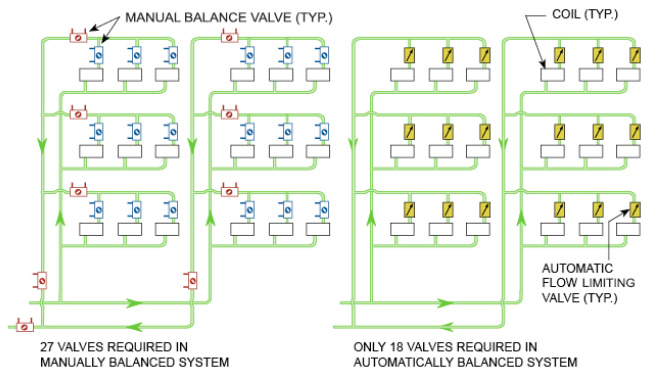
Figure 1
The manual system, shown above, requires a total of 27 valves whereas the automatic system, on the right, requires only 18 because it does not require the “partner balancing valves” (shown in red) on the risers and the branches.
As each terminal unit automatic flow limiting and pressure independent control valve is self-balancing over a wide differential pressure control range, the flow through the risers and the branches is also automatically controlled (balanced) without the use of additional valves.
Using 18 valves instead of 27 manual valves is approximately 1/3 savings in initial product purchases. In our previous example that is 27*$77 to $97.5 or $2,079 to $2,632.50 in manual valve costs. In comparison the automatic system costs 18*$70 or $1,260 in valve costs which is a substantial savings.
The elimination of the manual partner balancing valves on the mains, risers and branches in turn eliminates the head loss through them. Hence, the system head loss is reduced which lowers the pump head requirements.
System Stays Balanced Even During Reduced Load Conditions
No coil will starve when saving money by variable speed pumping. However, reducing the total water flow does not mean that all the coils in the building individually need the same reduction in flow. For example, on a typical spring day at 1:00 p.m., the total chilled water requirements of an 8-story office building will generally be much less than on a hot summer (design) day. However, the air-handler serving the filled-to-capacity cafeteria, on the first floor, will require almost 100% (of design) chilled water. A building with automatic flow limiting or pressure independent valves will give you this diversity whereas one with manual balancing valves cannot.
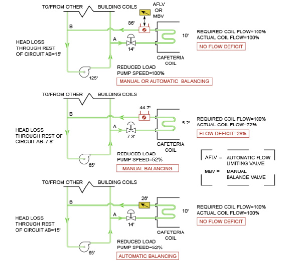
Figure 2
The schematic at the top shows the design load condition. The system operation point, at design load, is at (say) 125 feet of pump head. The head loss across the various elements (which adds up to 125 feet) for the cafeteria circuit, is as shown. Since the cafeteria is on the first floor, the head loss through the risers is negligible and is ignored.
Please note, for design flow at design head, the head loss through the manual balancing valve is the same as that through an automatic flow control valve (86 feet).
The schematic in the middle shows what happens when system flow is reduced (by lowering the pump speed to 52%), if the system is manually balanced. At the lower speed, the pump head will be smaller as will all the pressure losses. Since nothing else has changed in the cafeteria coil circuit, the head loss through the various elements will decrease proportionately and now add up to 65 feet instead of 125. Since the head loss through the manual flow control valve is reduced to 44.7 feet and since flow is proportional to the square root of the head loss, the flow through the manual balancing valve (and the coil) is reduced to 72% (square root of 44.7/86). There is NOW a flow deficit of 28%.
The schematic at the bottom shows what happens when system flow is reduced by the same amount if the system has automatic flow limiting valves. Again, the pump head decreases to 65 feet. However, the head loss distribution is not proportional. Instead, the cartridge inside the automatic flow control valve moves by a precise amount, to absorb only 26 feet of head and keeps the flow at the required 100%.
With the automatic flow limiting or pressure independent valve, there is no flow deficit at reduced system flow and reduced pump head.
(Note: In all three schematics of Figure 2, all losses in the pump room are ignored for clarity of discussion.)
Building Renovation Does Not Require Hydronic System Rebalance
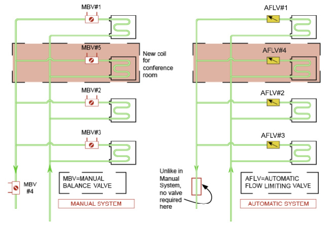
Figure 3
Very often, space renovation in an existing building also changes the heating/cooling requirements of that space. For example, an open office area that is converted into a large conference room will require more cooling due to the additional sensible and latent heat from the people. This may result in an additional fan-coil unit for the conference room. Figure 3 illustrates this scenario for a Manual vs. Automatic system.
If this is a manually balanced building, as shown in Figure 3 on the left side, valve MBV #5 would have to be added and manually set. However, doing this would change the flows through existing valves MBV #1 through MBV #4 and they would also have to be reset. Similarly, upstream branch/riser balancing valves (not shown) may also have to be reset. The resulting labor cost can be significant.
If this is a building with automatic flow control valves, as shown in Figure 3 on the right side, you would only have to add valve AFLV #4. Because these valves have wide control ranges, they would all automatically self balance to provide the required flows. No labor would be required to set the new valve or to reset any of the existing valves.
How does an Automatic Flow Limiting Valve Maintain Design Flow?
Griswold Controls designed the first balance valve in the market in 1960, years before the first manual balance valve was designed and manufactured. The all stainless steel flow limiting cartridge is a standard in the industry because of its simply elegant design.
When the differential pressure across the cartridge falls below its control range (pink colored area in Figure 4), the cup will come all the way out, exposing the maximum orifice area. Similarly, if the differential pressure across the cartridge rises.
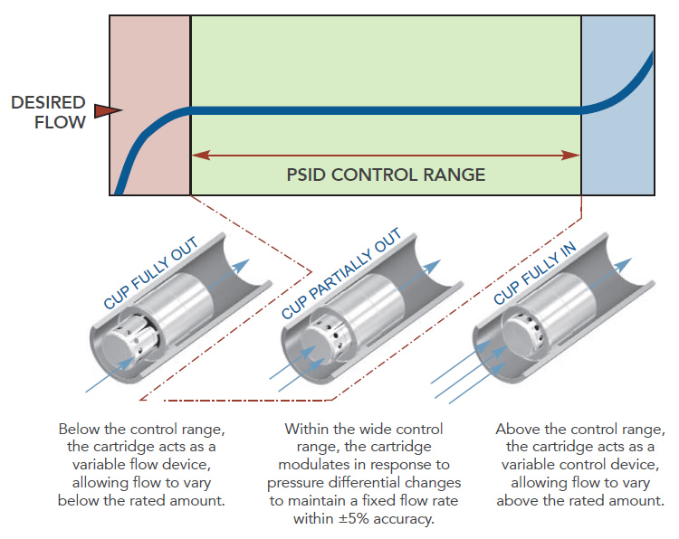
Figure 4
Above its control range (blue colored area in Figure 4), the cup will move all the way in, exposing the minimum orifice area. In both cases, the cartridge will now act as a fixed orifice device, varying flow based on the out-of-range differential pressure.
You do not have to worry about the cartridge ever shutting off the flow completely because a minimum orifice area is always open.